Barndoor Mounts for Astrophotography: the Motorized Version David Cortner
Motorizing the Barndoor Some false starts (belt drive is not the way to go, and you can't just stick any old potentiometer between a 9v battery and the motor and expect success) were followed by some good advice. Tom Nicolaides, NASA rocket scientist, really, urged me to use a PWM (Pulse Width Modulated) control circuit and provided what he thought of as simple instructions via email:
I had plenty enough sense to agree that a PWM controller was the way to go, but it's been a long time since E&M lab, so I bought a kit (eBay) to put a PWM circuit together. The PWM circuit comes from a "Future Kit" (model FK804 DC Motor Speed Control) which I bought from a model railroading vendor. Model railroaders use PWM circuits to start their trains with slow, realistic acceleration. Two trips to Radio Shack and some scavanging through the basement scrap pile produced a clean, motorized mount just begging for star tests. Easy is the word. It's easy to remove the motor if I want to go back to handcranking. And it's easy to power this drive from 9v batteries (light, compact, but low capacity). It will also be easy to power it from a 12v source (ubiquitous when traveling by car, always at hand when using CCD astro cameras or the equatorially mounted refractor). The motor is a Maxon 24 volt A-Max DC motor fitted with ~5000:1 reduction gears (eBay). It's 16mm in diameter and 55mm long. Tiny! To couple it to a drive bolt, I rethreaded a 10-24 shaft coupler (Ballard's Hardware Store) to 10-32 threads and then tapped a set screw into one side. A 10-32 bolt threaded into one end (and SuperGlued to stay the hell put) provides the barndoor's thrust bolt. The set screw locks the modified thread-coupler to the Maxon motor's shaft. The output shaft and the drive bolt are not perfectly concentric, but there's enough slippage and slack in the drive mounting arrangement that they're close enough.
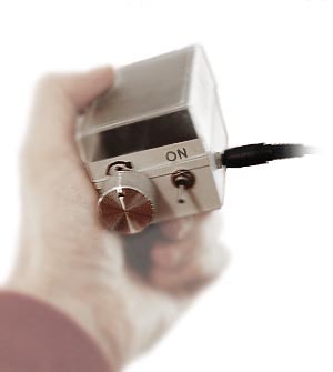
I managed to populate the circuit board without cooking any electronics and without requiring medical attention for molten metal burns (thank you David Close and E&M Lab) then mounted the board in a plastic case a photo processor used to return some 35mm slides. The control box has three external fittings: a knob for speed control, an on/off switch, and a power output socket (a 1/8-inch stereo jack). There's room inside for a 9v battery for power plus one or two spares. At the end of 12-15 minutes of tracking, the motor has to be reset by spinning it and its housing back down to their start position. Twirling the motor with the controller attached would be difficult; even twirling the motor with a cord attached would be vexing. So the controller and power supply connect to the motor using a stereo patch cord with 1/8-inch jacks on each end. That makes unhooking and reconnecting the power cord painless. It also means the cord is easy to replace (at any Radio Shack) if it gets lost after some sleep-depriving adventure in the dark. Setting the pot to produce an 80 second rotation is just a matter of timing the passage of the flats on the shaft coupler to get into the right ballpark and then timing a full rotation or two. The pot's knob is marked so it can be preset pretty closely. It takes a pretty hefty twist to make more than a few seconds difference, so the drive can be set precisely. A voltmeter might be used to set speed more quickly and to monitor changes as batteries fade and night air cools. O the Joy! Experiments in view.
The first time under the stars, I got trailing along a north-south line. I assumed at first this was due to a misalignment on the pole. But no: the trailing was not in declination, but a simple scalar smear, 5-6 pixels in the same direction all across a wideangle frame. Furthermore, it was just as bad in 1 minute as in 5. This has to be vibration. Is the motor resonating with the barndoor? I reduced the force of compression between the arms of the mount by removing one of the rubber bands and removing one of three twists from the remaining band. The motor runs more quietly, and the camera / mount / tripod combination does not feel nearly so "springy." That seems to have taken care of that, but it points out a direction for further improvements.
Here's a 4-minute exposure (10-22mm Canon lens at 10mm, iso 1600, F8) with Mars, the Pleiades, the Hyades, and a large sweep of the western sky, through thin fog. The lights of Rutherford College silhouette the pines. Click the image for a larger version. The stall in the motor is evident in the form of star trailing -- equivalent to about 6-8 seconds of unguided exposure -- when viewed at full resolution (which is about 10x bigger than this thumbnail). Stone Knives and Bearskins? Now that the 20-second pause between cranks no longer dominates the assortment of image faults, I am seeing liabilities due to the play in the hinge. It's probably time to find something better than a $3 strap hinge to provide a foundation. Doing things with twine and bailing wire has its own charm, but I'd rather have good tracking.
|

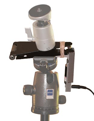
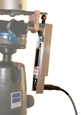
 The motor is press-fit inside a piece of aluminum channel (Lowe's Home Improvement Center, sold as cladding for 5/8-inch plywood). The cladding is lined with electrical tape to provide a tight fit and to prevent accidental shorts in the dark. A 1/8-inch stereo jack identical to one on the control box is attached to the channel to get power to the motor. The aluminum channel holding the motor slides freely within the next larger size of cladding (some judicious sanding and polishing made sure of the smoothness of that motion). Look at the photos to see how the larger piece of cladding provides a track for the motor housing to slide through and also restrains the motor from rotating (instead of rotating the drive bolt). Neat, hey? I thought the outer piece of cladding would have to be held in place by (yet another) rubber band, but so far it seems to fit well enough that it stays put without help.

