Barndoor Mounts for Astrophotography: Barndoor II David Cortner
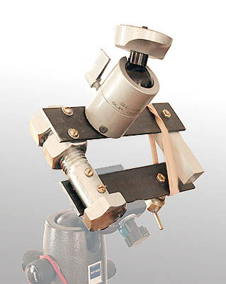
Barndoor II. I rebuilt the barndoor drive from the ground up. In place of the hinge is a 1-inch diameter bolt and a couple of hex nuts. I bolted two arms to this -- one to the shaft of the bolt, the other to one of the flats on the two hex nuts. (This gets tough to describe, so consult the photos.) It's much heavier, only slightly larger, and vastly smoother.
While trying to improve the motor mounting, I damaged the Maxon motor, repaired it, then damaged it again -- leads and attached brushes went flying. While cogitating on how to fix the motor or whether to replace it, I tested Barndoor Two using the manual drive bolt shown above. Works fine; the camera feels weightless. I made new brushes out of a multi-strand insulated wire and Superglued them in place; I made a weather-tight cap for the motor from scrap oak using a drill press and a table saw; I attached the leads to a 1/8-inch jack with plenty of strain relief this time. I scavanged a 10-32 t-nut from the old barndoor to extend the drive threads -- they felt too loose while messing with the longer moment arm of the motor and its bracket. The threads are better, but still not rock solid. On the bright side, maybe I need the play given that the drive shaft and the drive bolt are not perfectly aligned. I rigged up an automobile auxillary plug (remember when these were called "cigarette lighter adapters"?) so 9v batteries can be relegated to "emergency" use only. Other notes on electricity: apparently because of the new brushes, the motor requires more voltage to yield 80 seconds per rotation. At that speed, a voltmeter now shows 7.4 (used to be 7.1). Let me expose my naivete: I'm a little surprised that a voltmeter shows less than full voltage when using the PWM controller. The controller supplies 12 volts for a portion of each on-off cycle (there are 260 of these pulses per second). Live and learn. Just after nightfall, under a brilliant Moon, I went outside to try Barndoor II using Honda power. And nothing worked. I'd blown a fuse in the cigarette lighter adapter. I have no idea how. Hell, I had no idea it had a fuse. I rewired it so it doesn't. I didn't go back outside immediately to try it. If anything else broke, I thought I might lose my composure. I watched a movie ("Nosferatu," 1922). The motto of Barndoor 2 is, "do everything twice." While waiting for the Moon to get smaller, I trimmed the steel bars down to eliminate some weight and bulk and to keep the device out of the camera's way as much as possible. I moved the ball & socket closer to the axis of rotation, coated the threads with lithium grease, polished this and that, and generally got ready to give it a shakedown.
Under the Stars, at last: It works, and very well, too! I set the speed to 80 seconds per revolution, thinking I'd need to adjust that some -- if so, not by much. Alignment on the pole using an 8x50 finder and some aluminum bracketry was easy. A close look at my longest exposure -- of the summer Milky Way tilting down toward fall (the orange light on the pines is from Amy's Halloween lights) -- first suggested that the tracking rate was off by 1 or 1.5 percent. A closer look revealed that the critical issue was actually field rotation. That means the pole wasn't quite nailed when I aligned the mount. Tracking in Cygnus (near center) is close to dead on, but the field appears to rotate around a spot just right of center. The alignment bracketry on the pole finder must need some tweaking. A few minutes ago, I attached the polar alignment scope to a laser collimator using the same bracketry that is supposed to align it with the axis of the barndoor mount. Ideally, I should've been able to point the laser the length of the basement and the red dot would be a defocussed blur in the middle of the finder's field of view. It was off about 3 degrees. Couple of twists with pliers and a little judicious pushing and pulling got the error down to well under half a degree. Why didn't I didn't think to do this before? Galloping senility? Here's a visual depiction of my effort at proper alignment, offered not because it is particularly informative, but because it looks cool:
Now, let's find some projects to make all this effort worthwhile.
|


